Cabin Solar Wiring: Panels to Controller to Battery to Inverter
Affiliate disclosure: This page contains paid links to Amazon and eBay. If you buy through them, we may earn a commission at no extra cost to you. As an Amazon Associate I earn from qualifying purchases.
Wiring is where cabin solar systems are won or lost. The panels don't care how they're connected; the copper between them and your battery decides how much power survives the trip, and the fuses decide whether a fault is an inconvenience or a fire. None of it is hard — but all of it rewards doing in the right order with the right sizes.
This guide walks the complete electrical chain — array to controller to battery to inverter to loads — with the gauge, fusing, and sequencing rules that make a system safe, efficient, and easy to troubleshoot for the next twenty years.
The Chain, In Order
Every off-grid cabin system is the same five links:
Panels → [fuse/breaker] → Charge controller → [fuse] → Battery bank → [fuse] → Inverter → AC loads, with a [fused DC block] branching off the battery for 12V/24V loads like lights and pumps.
Two runs dominate the design: the array run (panels to controller), which can be long because it operates at higher voltage, and the battery-side runs (controller and inverter to battery), which must be short and thick because they carry high current at low voltage. Plan the physical layout around that asymmetry — controller and inverter within a few feet of the bank, panels wherever the sun is.
Series vs Parallel Panels
- Series (positive to negative, daisy-chained): voltages add, current stays constant. Thinner cable over long runs, but shade on one panel throttles the whole string, and total string voltage must stay under the controller's input ceiling — remembering cold mornings push panel voltage up 10–20%.
- Parallel (all positives together, all negatives together): current adds, voltage stays constant. Shade-tolerant and controller-friendly, but current climbs fast — thicker cable and a fuse on each string.
- Series-parallel — pairs in series, pairs paralleled — is where most 4+ panel cabin arrays land: enough voltage for an efficient run, enough parallelism to shrug off partial shade.
Let the controller decide: its input voltage window and amp rating define what topologies are legal. The MPPT guide covers the matching math.
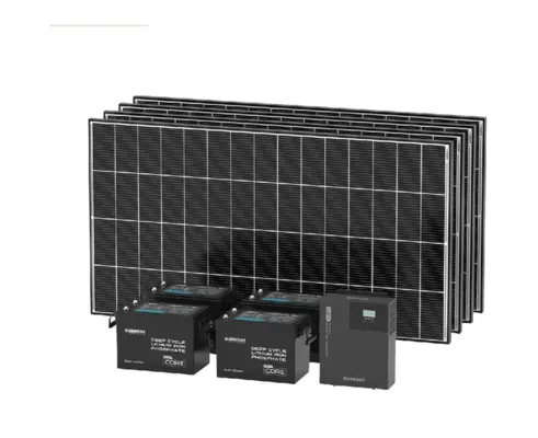 Renogy Cabin Solution — Complete Off-Grid Solar Kit →
Wire Gauge by Run
Copper is sized by current and distance. Undersized wire wastes harvest as heat and, at battery-side currents, becomes a hazard. Conservative working table for typical cabin systems:
| Run | Typical Current | Gauge (short runs) | Notes |
|---|---|---|---|
| Panel string (series, higher V) | 6–12A | 10 AWG solar cable | UV-rated; fine to 50–100 ft |
| Parallel array combiner to controller | 15–40A | 8–6 AWG | Grows with string count |
| Controller → battery | 20–60A | 6–4 AWG | Keep under ~6 ft |
| Battery → 2,000W inverter (12V) | up to ~200A | 2/0 AWG | The heavyweight run; under 3–6 ft |
| Battery → 2,000W inverter (24V) | up to ~100A | 1–2 AWG | Why bigger systems go 24V+ |
| DC fuse block → loads | 1–15A | 14–12 AWG | Per-circuit fusing at the block |
When in doubt, go one gauge thicker and follow your controller and inverter manuals — their tables account for the exact hardware.
Fusing: Every Positive, At the Source
- Main battery fuse (ANL, MRBF, or Class T for big lithium banks) within inches of the positive terminal — the fuse that protects everything.
- Inverter feed fuse sized to the inverter's max draw plus margin, per its manual.
- Controller-to-battery fuse at the controller's rated output.
- PV input fuse or breaker — a DC breaker here doubles as the array disconnect for service.
- Per-circuit fuses in the DC block for every light, pump, and outlet run.
12-Circuit DC Fuse Block with Negative Bus
The tidy heart of cabin DC wiring: twelve fused positive circuits and a negative bus bar in one labeled block, feeding every light, pump, USB outlet, and fridge run with its own correctly-sized fuse. Turns a rat's nest into a system.
ANL Fuse Holder + Fuse Assortment
High-current ANL fusing for the battery, controller, and inverter runs — the fuses that stand between a fault and a fire. Buy the holder, the working fuse, and a spare for each rating; the spare earns its keep the first time a fault finds you at dusk.
Connection Order and First Power-Up
Wire from the battery outward, panels last: bank assembled and fused → controller to battery (it should wake and show bank voltage; set the chemistry profile now) → inverter to battery through its fuse → DC loads through the block → array connected last, covered or at dusk. Then commission: verify voltages with a multimeter at each stage, add loads one at a time, and label every fuse and switch. The full checklist lives in the setup guide.
Renogy Cabin Solution — Complete Off-Grid Solar Kit →
Ground the panel frames and rails, bond per your inverter manual, and give lightning-prone sites a surge protection device on the PV input — cheap insurance on a ridge-top cabin.
Connectors, Crimps, and the Craft of Reliable Joints
Every wiring problem eventually resolves to a joint, so the craft details pay compound interest. Solar array connections use the standard weatherproof push-fit connectors on panel leads — buy a proper crimping tool for the pins rather than improvising with pliers, and always verify the click-lock engagement; a half-seated connector works in June and fails in the first freeze. Battery-side lugs deserve the same seriousness: tinned copper lugs, crimped with a hammer or hydraulic lug crimper, covered in adhesive heat-shrink. The joints to refuse: bare wire under terminal screws at high current, twist-and-tape anywhere, and dissimilar-metal contacts that invite corrosion. A tube of dielectric grease on outdoor connections and battery terminals is cheap insurance against the slow oxidation that presents, years later, as mysterious voltage sag. Good joints are why twenty-year-old systems still work; bad ones are why five-year-old systems don't.
A Worked Wiring Example, End to End
Putting the rules together on the guide's example system — 800W of panels, 24V bank, 40A MPPT, 2,000W inverter: the eight panels wire as four series pairs paralleled (each pair ~40V), giving the array a working voltage comfortably inside a 100V controller window with cold margin. The array home-run to the controller carries ~20A over 10 AWG solar cable, protected by a DC breaker that doubles as the array disconnect. Controller to bank: four feet of 6 AWG through a 50A fuse. Bank to inverter: three feet of 1 AWG through a 125A ANL fuse, with the main battery fuse and disconnect switch inboard of everything. DC loads run from a 12-circuit fuse block fed at 24V (or via a small 24-to-12V converter for legacy 12V accessories). Every positive fused at its source, every run labeled, the whole chain commissioned battery-first per the setup guide. That paragraph is the entire electrical design of a very good cabin system.
Renogy Cabin Solution — Complete Off-Grid Solar Kit →
Frequently Asked Questions
What gauge wire do I need from solar panels to the charge controller?
For a series string carrying 6–12A, 10 AWG UV-rated solar cable handles runs of 50–100 feet with minimal loss. Parallel arrays push more current and step up to 8–6 AWG. The controller-to-battery run is the one that demands thick copper — 6–4 AWG kept under about six feet.
Should cabin solar panels be wired in series or parallel?
Series suits long runs and clear-sky sites: voltage adds, cable stays thin. Parallel tolerates the shade that tree-ringed cabins face, at the cost of thicker cable and per-string fuses. Most arrays of four or more panels use series-parallel pairs — and the controller's voltage window makes the final call.
What fuses does an off-grid solar system need?
Every positive conductor gets a fuse at its source: a main battery fuse at the positive terminal, a fuse on the inverter feed, one on the controller-to-battery run, a PV breaker or fuse on the array input, and per-circuit fuses in the DC block. A battery disconnect switch belongs in the build too.
Why do bigger cabin systems use 24V or 48V?
Doubling bank voltage halves the current for the same power, which shrinks wire gauge, fuse size, and resistive losses across the whole battery side. Above roughly 500W of array or 2,000W of inverter, 24V wiring is dramatically easier; whole-home scale goes 48V for the same reason.
What order do I connect solar wiring?
Battery first, then charge controller to battery, then inverter, then DC loads — and the panels absolutely last, covered or after dusk. Controllers must see battery voltage before panel voltage to configure correctly, and several models can be damaged by array-first connection.